Constant Pressure Drilling Fluid Mud Gas Separator
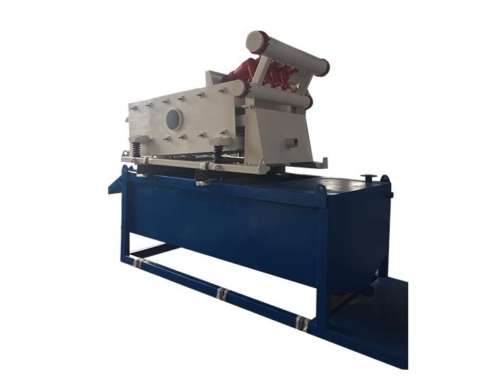
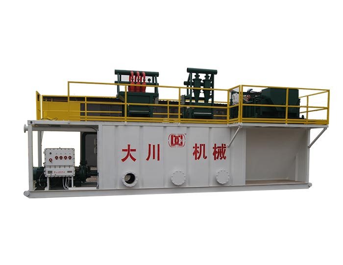
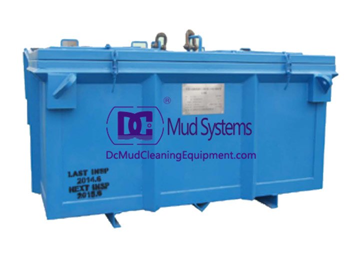
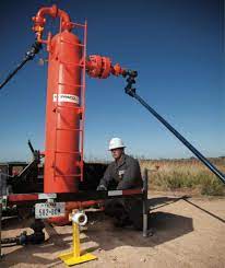
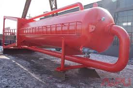
- Constant pressure drilling fluid mud gas separator is a specialized equipment used for primary degassing of gas-cutting drilling fluid.
The mud/gas separator is designed to provide effective separation of the mud and gas circulated from the well by venting the gas and returning the mud to the mud pits.
The mud gas separator is designed to provide effective separation of the mud and gas circulated from the well by venting the gas and returning the mud to the mud pits. Small amounts of entrained gas can then be handled by a vacuum-type degasser located in the mud pits. The mud/gas separator controls gas cutting during kick situations, during drilling with significant drilled gas in the mud returns, or when trip gas is circulated up.
Features and Benefits of Mud Gas Separator
1. Constant pressure drilling fluid mud gas separator is a specialized equipment used for primary degassing of gas-cutting drilling fluid,it is mainly used to remove big bubbles whose diameter ≥φ3mm.
2. Mud gas separators produced by DC have the advantages of safety and reliability,good treatment effect,long service life ,etc.
3. Constant pressure Anti-H2S drilling fluid mud gas separator manufactured by DC adopts high quality material , can effectively prevent the erosion of harmful gas and ensure production safety of man and machine.
4. The separated gas is transported to a safe area by the discharge line for combustion.
Mud Gas Separator Parameters
Model | DCZYQ800 | DCZYQ1000 | DCZYQ1200 |
Treating capacity | 200~260m3/h | 240~300m3/h | 280~360m3/h |
Main body | 800mm | 1000mm | 1200mm |
Tank wall thickness | 10mm | 10mm | 12mm |
Inlet | 5" | 5" | 5" |
Outlet | 8" | 8" | 10" |
Vent-pipe | 8" | 8" | 8" |
Dimension | 1600×1600×5720mm | 2000×2000×5920mm | 2200×2200×6634mm |
Weight | 1600kg | 2100kg | 3200kg |
Operation Principle of Mud Gas Separator
The operating principle of a mud gas separator is relatively simple. The device is essentially a vertical steel cylindrical body with openings on the top, bottom, and side. The mud and gas mixture is fed into the separator inlet and directed at a flat steel plate perpendicular to the flow. This impingement plate minimizes the erosion wear on the separator’s internal walls and assists with mud/gas separation. Separation is further assisted as the mud/gas mixture falls over a series of baffles designed to increase the turbulence within the upper section of the vessel. The free gas is then vented through the gas vent line, and mud is returned to the mud tanks.
Operating pressure within the separator is equal to the friction pressure of the free gas venting through the vent line. Fluid is maintained at a specific level (mud leg) within the separator at all times. If the friction pressure of the gas venting through the vent line exceeds the mud-leg hydrostatic pressure within the separator, a blow-through condition will result in sending a mud/gas mixture to the mud tanks. As one can readily see, the critical point for separator blow-through exists when peak gas flow rates are experienced in the separator. Peak gas flow rates should theoretically be experienced when gas initially reaches the separator.
Mud Gas Separator Considerations
1. Gas kicks in oil-based mud can approach “possibly soluble” conditions while the kick is circulated from the well.
2. Gas kicks in Mud Gas Separator that pass through the gas bubble point while being circulated from the well can experience higher Pcmax and Vcmax values than were calculated for a kick of the same initial pit gain in a water-based mud. This results in higher peak gas flow rates through the separator and thus the requirement for a more stringent separator design.
3. Gas kicks in Mud Gas Separator that do not pass through the gas bubble point until the gas is downstream of the choke will severely affect mud/gas separator sizing and design. Peak gas flow rates will be extremely high relative to those calculated for water-based mud, as outlined in this paper. Additional evaluation of the separator sizing should be completed if these good conditions exist.
We will provide you with the most professional technical advice and complete after-sales service. The products have passed ISO 2000 certification and are absolutely worthy of your trust. You can always click here to learn more about us.
Why Are Super Mud Gas Separators Preferred in High-Pressure Wells?
High-pressure wells demand precise handling of mud and entrained gases, which makes the super mud gas separator an indispensable tool. Tangshan Dachuan Machinery Co., Ltd., as experienced mud gas separator manufacturers, provide products optimized for rigorous conditions. The mud gas separator design integrates advanced venting systems to prevent gas accumulation while returning clean mud to the pit, maintaining drilling fluid consistency. Accurate mud gas separator sizing calculations are applied to ensure that each separator handles gas flow effectively during mud gas separator drilling operations. Our china mud gas separator combines safety, efficiency, and ease of maintenance, making it suitable for extended drilling campaigns. By partnering with a reliable mud gas separator supplier, operators can ensure that their equipment meets stringent performance and safety standards. The mud gas separator price offered reflects superior engineering and durability, delivering long-term value. Implementing a mud gas separator from Tangshan Dachuan Machinery Co., Ltd. allows operators to manage gas cuts efficiently, enhance drilling speed, and minimize operational interruptions. The result is a safer, more predictable drilling environment that aligns with global industry expectations.
How Does Mud Gas Separator Sizing Affect Drilling Performance?
Proper mud gas separator sizing calculations are fundamental to ensuring that a Mud Gas Separator performs efficiently. Tangshan Dachuan Machinery Co., Ltd., recognized mud gas separator manufacturers, design each unit to handle site-specific gas volumes without compromising mud circulation. Using the correct mud gas separator ensures that gas is vented safely, protecting both personnel and equipment during mud gas separator drilling. Our super mud gas separator incorporates engineering innovations that enhance separation efficiency and reduce downtime. By partnering with a trusted mud gas separator supplier, operators gain access to equipment tailored for depth, pressure, and flow requirements, maximizing operational efficiency. The mud gas separator price reflects not only production quality but also optimized performance, ensuring cost-effective risk mitigation. Thoughtful mud gas separator design is crucial to prevent gas accumulation and maintain wellbore stability. Operators relying on Tangshan Dachuan Machinery Co., Ltd. benefit from reduced environmental hazards, improved drilling precision, and reliable system performance, making our separators a vital component in modern drilling operations.
What Features Make Mud Gas Separators a Smart Investment?
Choosing a mud gas separator from Tangshan Dachuan Machinery Co., Ltd. combines advanced engineering with operational reliability. Our mud gas separator design emphasizes effective mud and gas separation, maintaining consistent drilling fluid quality even during high-gas scenarios. Accurate mud gas separator sizing calculations ensure that each unit meets the specific demands of mud gas separator drilling, preventing blockages or gas-induced interruptions. The super mud gas separator integrates venting and return systems for safety and efficiency. Partnering with leading mud gas separator manufacturers ensures access to expertly engineered equipment, supported by comprehensive after-sales service. Selecting a reliable mud gas separator supplier ensures timely delivery and technical support, while the competitive mud gas separator price makes it a practical choice for drilling projects. The result is reduced downtime, enhanced safety, and optimized operational efficiency. Investing in Tangshan Dachuan’s Mud Gas Separator provides measurable benefits: maintaining drilling fluid integrity, controlling gas cuts, and minimizing risk for crews and equipment alike.
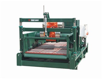 Linear Motion Shale Shaker In Drilling Rig
 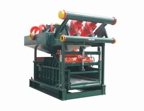 Oilfield Mud Cleaner
 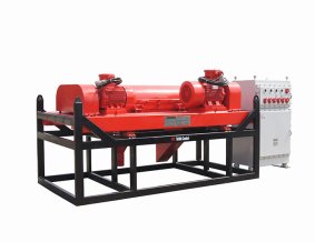 Drilling Fluid Decanter Centrifuge
 Drilling Mud Desander
Hydrocyclone Desilter
Centrifugal Pump/Centrifugal Mud Pump
Shear Pump
Jet Mud Mixer
Horizontal Mud Agitator
Constant Pressure Drilling Fluid Mud Gas Separator
Mud Gun
 Mud Tank
 Solids Control System Vacuum Degasser
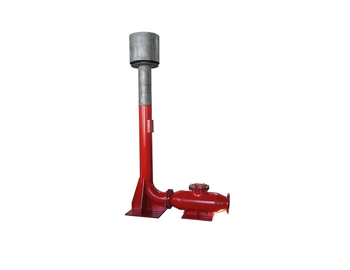 Flare Ignition Device
 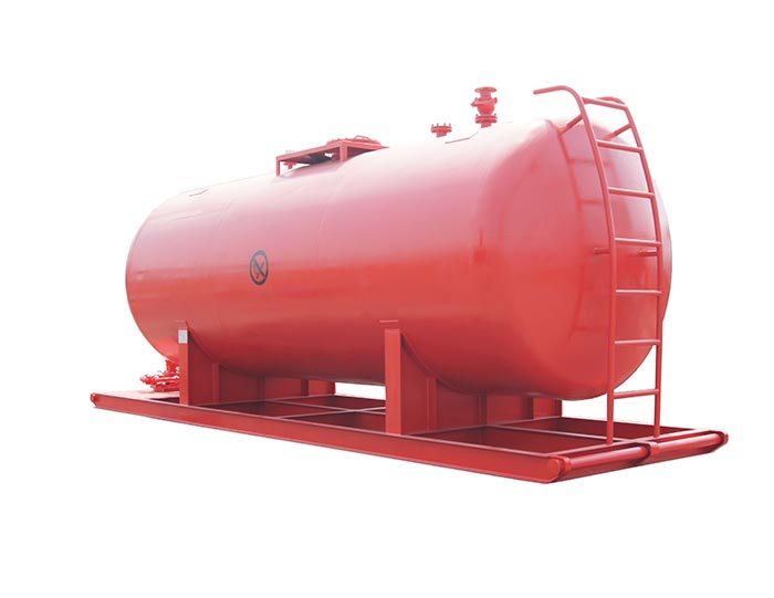 Diesel Tank
 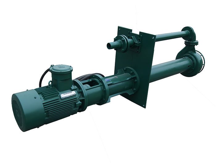 Submersible Slurry Pump


